arrow diagram notation
Since Arrow Diagramming is also called “activity-on-the- arrow” it should come as no surprise that the primary element of an arrow diagram is a set of arrows. One arrow is required for each activity. The tail of the arrow is the start of the activity. The head of the arrow is the completion of the activity.
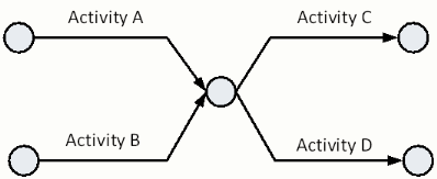
Since we want the diagram to show sequence, “nodes” are placed at the tail and head of each activity arrow. To illustrate how the nodes are used to show sequence between activities, the illustrations below show several different schedule fragments.
example 1
| Activity | Prior Activity |
|---|---|
| A | None |
| B | A |

example 2
| Activity | Prior Activity |
|---|---|
| A | None |
| B | A |
| C | A |

example 3
| Activity | Prior Activity |
|---|---|
| A | None |
| B | None |
| C | A, B |
| D | A, B |

The combination of all activities in a schedule is called a “network.” An arrow diagram for a complete project may also be referred to as a network diagram. One of the characteristic factors of projects (as opposed to processes) is that projects should a single start node and end node. With a single start and end node, the start date and finish date of projects may be clearly shown in diagrams and easily identified on scheduling software reports.
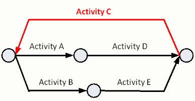
An example of an incorrect application of Arrow Diagramming is shown below. The arrow for Activity C starts at the end of the project and ends at the start of the Project. The kind of activity listing should be considered a “process” and not a project. Regardless of the technique, Arrow Diagramming or Precedence Diagramming, the Critical Path Method cannot include “loops.”
| Activity | Prior Activity |
|---|---|
| A | None |
| B | None |
| C | D, E |
| D | A |
| E | B |
