precedence diagramming
Precedence Diagramming, or the Precedence Diagram Method,
alleviates the difficulties of combining the representation
of sequence and duration. Precedence Diagramming was
originally referred to as “activity on node.”
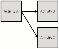
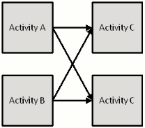
In Precedence Diagramming the activities are identified by
“nodes” or blocks. The sequence between activities is
shown by arrows. The example below shows the schedule
fragments previously shown for Arrow Diagrams.
example one
| Activity |
Prior Activity |
| A |
None |
| B |
A |

example two
| Activity |
Prior Activity |
| A |
None |
| B |
A |
| C |
A |

example three
| Activity |
Prior Activity |
| A |
None |
| B |
None |
| C |
A, B |
| D |
A, B |

A precedence diagram without any network calculations, such as that
shown in the figures above, may be called "layout" diagrams. The layout
diagram is a simple drawing that allows you to quickly sketch the
sequence of activities in a network. Once the network has been sketched,
then you can identify and correct lines that cross over and aesthetically
organize the position of each.
While scheduling software is able to
produce diagrams showing the activities and sequence, projects with
complex sequence will require significant “tinkering” with the ordering
of activities to generate a computer-generated printout that clearly
communicates the sequence of the project.
examples for you to try
| Activity |
Prior Activity |
| A |
None |
| B |
A |
| C |
A |
| D |
B, C |
| Activity |
Prior Activity |
| A |
None |
| B |
None |
| C |
A |
| D |
A, B |


